Low Power Braking Solutions
The measure of a man is what he does with power. —Plato
I am sure that when the ancient Greek philosopher expressed that, he wasn’t thinking about motion control, electrification and batteries in our modern world. The quote holds true today, but this time it’s P=VI and I2R.
Key points:
- Power can be saved while using electromagnetic brakes
- Cooler is better
- Optimization through customization
The Basics - Electromagnetic Spring Applied Brake:
These brakes operate mechanically, but actuate electrically. Without power applied, they stop or hold a shaft in place to prevent rotation. A good example of this is a parking brake. When you apply power, the brake releases allowing rotation. Here is a video showing how they work. Image 1.
https://ogura-clutch.com/video-springapplied.php
Who wants more power?
With the rapid adaption of mobile robotics and battery powered equipment, the value of power has never been greater. When dealing with electromagnetic brakes for these applications, the goal is to reduce power draw as much as possible. This allows more power for essential equipment operation, longer battery life, lower cost of operation, and a healthier environment.
How do I limit power draw from the brake?
1) Customize to optimize
2) Keep it cool
3) Keep it light
4) Use a power controller
How do you customize a brake?
Leading brake manufacturers like Ogura have the engineering expertise and application experience to navigate you through it. Submit your application here for initial review.
https://ogura-clutch.com/application-data-form.php
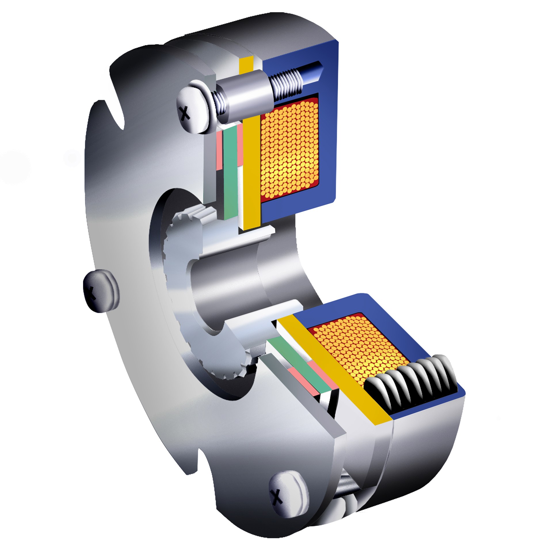
While the basic principles of electromagnetic brake operation won’t change, some design modifications can be made to give the performance required. Air gaps, spring force, materials, coils, and flux paths can be optimized. Image 2.
Pulse Width Modulation:
Magnetic flux takes the path of least resistance. When current is applied, the brake disengages and the inductance changes. This transpires in a matter of milliseconds, depending on the brake size and design.
From a mechanical perspective, at this disengaged brake state, the pressure plate is contacting the coil body. Furthermore, the magnetic flux no longer needs to jump a distance (air gap).
(Image 3 shows a standard spring applied brake with the pressure plate held up against the coil body when the coil is energized).
At this point, power can be reduced to hold the brake in this disengaged state. Electric current should maximize the work that it performs, but also minimize wasted power.
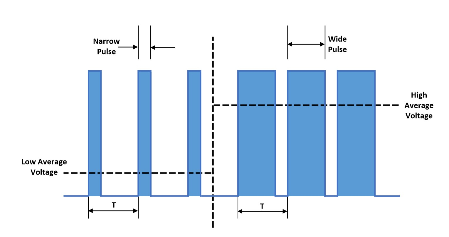
Through pulse width modulation, PWM, draw back the power to keep the brake disengaged. Generally speaking, there is usually a savings of at least 50% power through this method. Some 24V brakes can average down to about 7V, which is closer to 70% savings.
(Image 4 shows low average voltage with PWM).
Over-excitation:
Over-excitation provides optimum torque for a given size. It is the metaphorical equivalent of fitting 10 pounds of something into a 5 pound bag. For example, when disengaging a spring applied brake with a 12V coil, apply 24V for a very short duration while the coil magnetically attracts the pressure plate and compresses the springs. The required power is reduced once the pressure plate is contacting the coil body.
If over-excitation is used in an application, it is important that the brake coil is designed for this type of operation. The desire is to have long lasting products that meet life expectations. Image 5.
(OCP25 type power supply is an overexcitation/weak excitation power supply for the PWM control method for power-off brakes. For the MCNB-T series brakes, the armature’s actuation is faster by overexcitation and the brake can be released quickly. In addition, weak excitation can reduce the rise of brake temperature and power consumption.)
Keeping cool:
By combining over-excitation and PWM, it reduces total average voltage on the brake, thus eliminating excess heat buildup in the coil. Heat is the result of this wasted energy.
As the temperature goes up, so does resistance. In a constant current situation, when resistance rises, so does the power requirement. To prevent wasted power, keeping cool is the way to go.
Limiting weight:
There’s no point in carrying extra weight unless you are designing something like a steamroller. While it would be easy to employ a brake with a large surface to dissipate heat, it just isn’t practical in most mobile applications. The real focus is on eliminating excess weight in mobile robotics and electrification projects. Lower weight will require less effort/power from the drive train and could also result in improved response time or overall performance.
Weight can be reduced by eliminating parts. The brake can be built into the motor end bell. Weight can be reduced by removing unneeded material from a brake flange. Brakes should be designed for a particular application to meet torque, temperature, speed, inertia, duty cycle, mounting, etc. Customization leads to optimization in performance while minimizing weight.
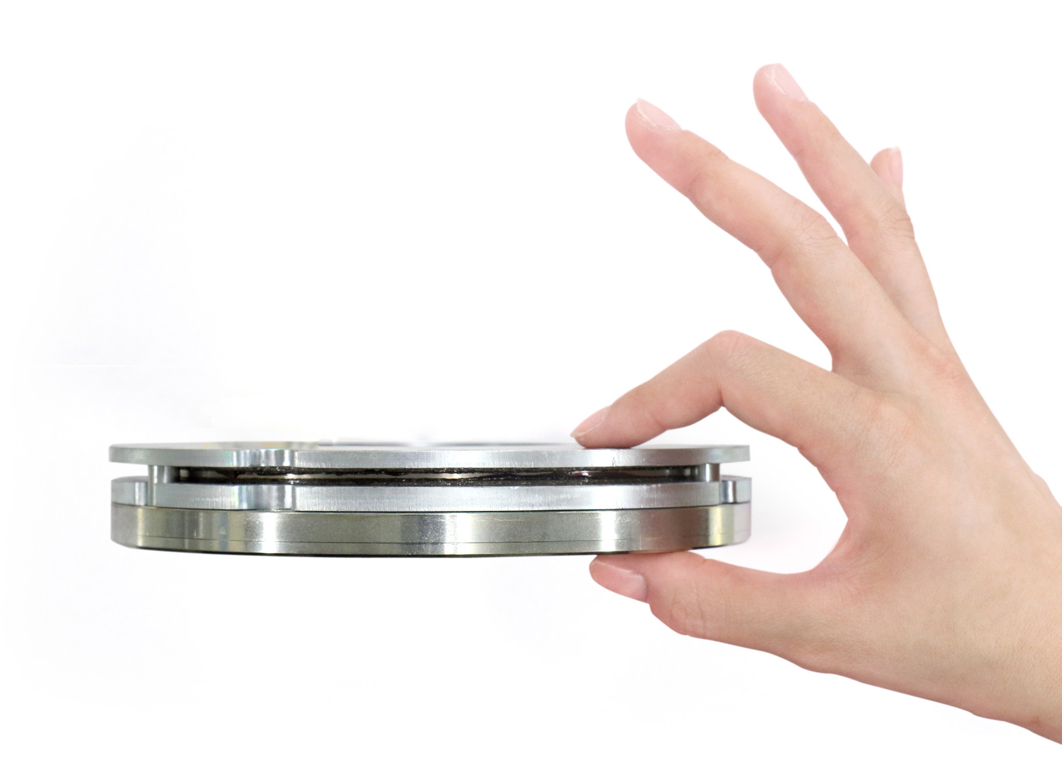
(Image 6 shows thin brakes that have comparable torque but much thinner profile and weight).
Bi-Stable brakes:
There exists another braking solution that provides great power-saving potential. Duty cycle is an important factor in determining benefits since fewer actuation events lead to greater energy conservation. Bi-stable brakes actuate when a pulse of power is sent to the brake, changing its state from engaged to disengaged or vice versa.
This type of technology has been used for years on applications such as solar wings on a satellite. Traditionally, these applications required limited cycles over a lifetime. There are some newer applications like water pump clutches on vehicles that can use this technology. The pump is normally engaged but occasionally disengaged to help with emissions when the engine is cold.
The same power savings approach can apply to an AGV, electric vehicle, mobile robot, but power comes at a cost. Bi-stable designs typically utilize permanent magnets to obtain the functionality. The components can be expensive when compared to standard spring applied brakes. The advantages and disadvantages should be evaluated early in the design process for the best path forward. A combination of torque, size, weight, temperature, performance and cost should be considered.
Conclusion:
If you want the smallest, lightest, lowest power brake available, talk to your preferred brake supplier in the earliest stages of your design project. Waiting until later in the design process will trigger a compromise on one or all three of these important design considerations.
Brian Mather, Ogura Industrial Corp, bmather@ogura-clutch.com
Industrial Product Manager, Regional Sales Manager
Lennie Iuliano, PALS-SALES, lennie.iuliano@pals-sales.com
Industrial Sales Manager